Sony DSC W55 - Cyber-shot Digital Camera driver and firmware
Drivers and firmware downloads for this Sony item
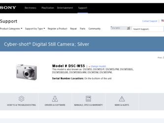
Related Sony DSC W55 Manual Pages
Download the free PDF manual for Sony DSC W55 and other Sony manuals at ManualOwl.com
Instruction Manual - Page 2
English
Owner's Record
The model and serial numbers are located on the bottom. Record the serial number in the space provided below. Refer to these numbers whenever you call upon your Sony dealer regarding this product. Model No. DSC-W35/W55 Serial No
WARNING
To reduce fire or shock hazard, do not expose the unit to rain or moisture...
Instruction Manual - Page 3
... from the wall outlet and disconnect the antenna or cable system. This will prevent damage to the set due to lightning and power-line surges.
Service
[ Damage Requiring Service
Unplug the set from the wall outlet and refer servicing to qualified service personnel under the following conditions: - When the power cord or plug is damaged or
frayed. - If liquid...
Instruction Manual - Page 5
... from that to which the receiver is connected. - Consult the dealer or an experienced radio/TV technician for help.
The supplied interface cable must be used with the equipment in order to comply with the limits for a digital device pursuant to Subpart B of Part 15 of FCC Rules.
For the State of California, USA...
Instruction Manual - Page 7
... Indicators on the screen 19 Changing the settings - Menu/Setup 21
Menu items 22
Setup items 23 GB Enjoying your computer 25
Supported Operating Systems for USB connection and application software (supplied 25 Viewing "Cyber-shot Handbook 25
Battery life and memory capacity 26
Battery life and number of images that can be recorded/viewed .......... 26 Number of still images and...
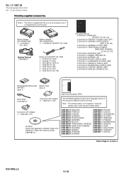
Instruction Manual - Page 9
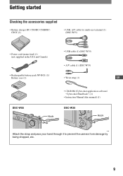
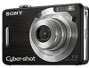
... (1) (DSC-W55)
• Power cord (mains lead) (1) (not supplied in the USA and Canada)
• USB cable (1) (DSC-W35) • A/V cable (1) (DSC-W35)
• Rechargeable battery pack NP-BG1 (1)/
Battery case (1)
• Wrist strap (1)
GB
DSC-W55
Hook
• CD-ROM (Cyber-shot application software/ "Cyber-shot Handbook") (1)
• Instruction Manual (this manual) (1)
DSC-W35
Hook...
Instruction Manual - Page 25
... OS does not support USB connections, use a commercially available Memory Stick Reader/Writer.
• For further details on the operating environment of Cyber-shot application software, "Picture Motion
Browser", refer to "Cyber-shot Handbook."
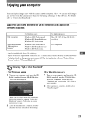
Viewing "Cyber-shot Handbook"
[ For Windows users
1 Turn on your computer, and insert the CD-
ROM (supplied) into the CD-ROM drive. The screen below...
Instruction Manual - Page 29
... screen, refer to "Cyber-shot Handbook."
2 Remove the battery pack, and insert the battery pack again after about one minute, and turn on the power.
3 Initialize the settings (page 24).
4 Consult your Sony dealer or local authorized Sony service facility.
Please understand that you give your consent that the contents of the internal memory may be GB
checked...
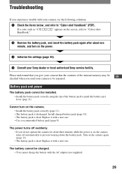
Instruction Manual - Page 30
... the battery pack to correct the display. • The battery pack is discharged. Install the charged battery pack (page 10). • The battery pack is dead. Replace it with a new one.
Shooting still images/movies
Your camera cannot record images. • Check the free capacity of the internal memory or "Memory Stick Duo" (pages 27, 28...
Instruction Manual - Page 33
... PRO
Duo",
, "Memory
Stick Micro", "MagicGate", and
are trademarks of Sony
Corporation.
• Microsoft, Windows and DirectX are either
registered trademarks or trademarks of
Microsoft Corporation in the United States and/
or other countries.
• Macintosh, Mac OS, iMac, iBook, PowerBook,
Power Mac and eMac are trademarks or
registered trademarks of Apple Computer, Inc.
•...
Service Manual - Page 3
...201;MENTS PUBLIÉS PAR SONY.
SAFETY CHECK-OUT
After correcting the original service problem, perform the following safety checks before releasing the set to the customer.
1. Check...Some printed circuit boards may not come printed with the lead free mark due to their particular size.)
3. Look for unauthorized replacement parts, particularly
transistors, that were installed during a previous ...
Service Manual - Page 8
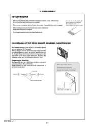
... at wire of connector. It is possible that a wire is snapped.
• When installing a connector, dont' press down at wire of connector. It is possible that a wire is snapped.
• Do not apply excessive load to the gilded flexible board.
Cut and remove the part of gilt which comes off at the point...
Service Manual - Page 12
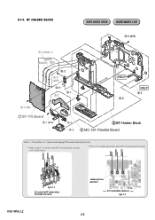
... (#5)
3-2
1-3 (#20)
3-3 3-1
1-2
MC-181
HELP 3-6
HELP 3-5
1 SY-176 Board
2-1 (#20)
2-3 2-2
3 BT Holder Block 2 MC-181 Flexible Board
Note 1 : Precaution 1-4 when exchanging BT terminal board (service)
Refer to fig.2-1-1, when install BT terminal board (service) in BT holder block.
Fig.2-1-2 is soldering position about BT terminal board (service).
BLACK WHITE RED
RED WHITE BLACK
1 2
fig...
Service Manual - Page 13
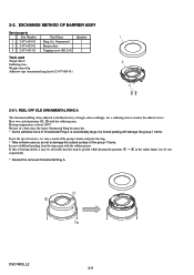
2-2. EXCHANGE METHOD OF BARRIER ASSY
Service parts Part Number
1 2-673-650-01 2 2-673-652-01 3 2-673-651-01
Part Name Ring (A), Ornamental Barrier Assy Tapping screw (B1.2×4)
Quantity 1 1 2
Tools used Torque driver Soldering iron Weight about 60g Adhesive tape (ornamental ring fixed) ... under figure one by one sequentially.
* Discard the removed Ornamental Ring A.
1 2
Tip
DSC-W55_L2 2-6
Service Manual - Page 14
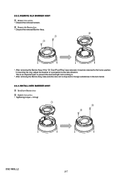
... dust and light from coming in.
* After removing the Barrier Assy, take extreme care not to drop dust or foreign substances in the lens barrel.
2-2-3. INSTALL NEW BARRIER ASSY 1 Install new Barrier Assy. 2 Tighten two screws. * Tightening torque = 0.5 kgf...
Service Manual - Page 16
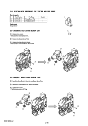
... UNIT
Service parts Part Number
1 2-673-648-01 2 2-673-649-01
Part Name Zoom Motor Unit BT2 P1.4×3 B3C
Quantity 1 2
Tools used Torque driver
2-3-1. REMOVE OLD ZOOM MOTOR UNIT
1 Remove two screws. * Discard the removed screws.
2 Remove the Zoom Motor Unit.
3 Remove the Lens Flexible Board. * Discard the removed Zoom Motor Unit.
1 2
2
3
1 3 3
1
2-3-2. INSTALL...
Service Manual - Page 21
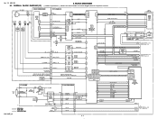
... MOTOR DRIVER
G1, E4
MSHUT_DIR, MSHUT_EN
FC_SENS, XFC_RST_LED
ZM_DC_FG_1A, ZM_DC_FG_1B, XZM_FG_LED, ZM_SENS_1ST,XZM_RST_LED
LENS TEMP SENSOR
30
LENS_TEMP J25
FLASH UNIT
ST-133 BOARD
XE_H
TRIGGER TRIGGER_GND
D002
C901 CHARGING + CAPACITOR
T001
5
4
1
3 2
XE_L
Q001 FLASH DRIVE
08
: VIDEO SIGNAL : AUDIO SIGNAL : VIDEO/AUDIO SIGNAL
1, 2
ST_UNREG
15 IC001 10 9
FLASH CONTROL, CHARGE...
Service Manual - Page 23
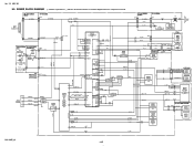
...
T001
D002
IC001 FLASH CONTROL, CHARGE CONTROL
LCD901 LCD UNIT
31,32
L901 L902
D_3.2V M_5V
CN901 25
D_3.2V
CN705 BL_H (2/2) 23
BL_H
CN003(2/2) (LND002) 1
BL_L
BL_L
21
2
(LND001)
RL-074 FLEXIBLE SW-498 BOARD
BOARD (2/2)
(2/2)
2.5 INCH DIGITAL
LCD MONITOR
LCD BACKLIGHT
AU_3.0V M_5V
IC603
AUDIO AMP (5/6)
FLASH UNIT
IC401
LENS DRIVE, MOTOR DRIVER
(3/6)
CAM_- 7.5V
CAM_12V...
Service Manual - Page 43
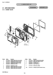
...-618-1 CABINET (REAR) ASSY (240) (BLUE)
Ref. No.
4 5 6 7 *8
Part No.
Description
X-2176-619-1 CABINET (REAR) ASSY (240) (PINK) 3-093-831-01 SHEET (240), WINDOW ADHESIVE 3-093-842-01 WINDOW (240), LCD 3-093-834-01 LID (PLATE), DC 3-093-810-01 LABEL, FUSE RATING
9
3-100-146-01 SPACER (240), MOARE
#20 2-635-591...
Service Manual - Page 49
...-007-11 (JE)
The CD-ROM supplied contains all of language version of the instruction Manual in pdf for printing.
Note : The printed matter is not supplied. If required, please order it with the part number below.
Conversion (2P) Adaptor 0 1-569-008-11 (E)
CD-ROM (Cyber-shot application software/"Cyber-shot Handbook"/"Cyber-shot Step-up Guide) 2-899-984-02
2-899-987-11...
Service Manual - Page 59
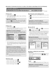
...Reader Ver5.0 (for Windows)]
Toolbar
Printing a text 1. Click the Print button . 2. Specify a printer, print range, number of copies, and other op-
tions, and then click [OK].
Application of printing: To set ... or printed circuit board diagram successively. Note: The find function may not be applied to the Service
Manual depending on the date of issue.
Reversing the screens displayed once •...