Dell Alienware Area 51 R2 driver and firmware
Drivers and firmware downloads for this Dell item
Related Dell Alienware Area 51 R2 Manual Pages
Download the free PDF manual for Dell Alienware Area 51 R2 and other Dell manuals at ManualOwl.com
Service Manual - Page 10
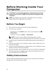
... cables such as telephone cables, network cables and so on, from your computer.
5 Disconnect all attached devices and peripherals, such as keyboard, mouse, monitor, and so on, from your computer.
6 Remove any media card and optical disc from your computer, if applicable. 7 After the computer is unplugged, press and hold the power button for 5
seconds to ground the system board.
Safety Instructions...
Service Manual - Page 12
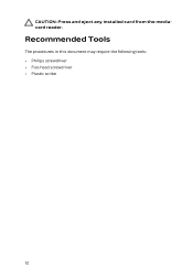
CAUTION: Press and eject any installed card from the mediacard reader.
Recommended Tools
The procedures in this document may require the following tools: • Philips screwdriver • Flat-head screwdriver • Plastic scribe
12
Service Manual - Page 14
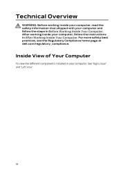
... the steps in Before Working Inside Your Computer. After working inside your computer, follow the instructions in After Working Inside Your Computer. For more safety best practices, see the Regulatory Compliance home page at dell.com/regulatory_compliance.
Inside View of Your Computer
To view the different components installed in your computer. See "Right View" and "Left View".
14
Service Manual - Page 39
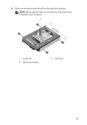
6 Slide and remove the hard drive from the hard-drive bracket.
NOTE: Repeat step 2 to step 5 to remove any other hard drives installed in your computer.
1 screws (4) 3 hard-drive bracket
2 hard drive
39
Service Manual - Page 40
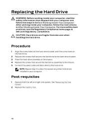
... screws that secures the hard drive to the hard-drive bracket. 3 Place the hard-drive assembly in the chassis. 4 Replace the screws that secure the hard-drive assembly to the chassis. 5 Connect the power cable and data cable to the hard-drive.
NOTE: Repeat step 2 to step 5 to replace any other hard drives installed in your computer.
Post-requisites
1 Replace both...
Service Manual - Page 63
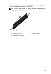
4 Grasp the memory module near the securing clip, and then gently ease the memory module out of the memory-module slot.
NOTE: Repeat step 2 to step 3 to remove any other memory modules installed in your computer.
1 securing clips (2) 3 memory-module slot
2 memory module
63
Service Manual - Page 67
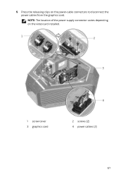
5 Press the releasing clips on the power-cable connectors to disconnect the power cables from the graphics card.
NOTE: The location of the power supply connector varies depending on the video card installed.
1 screw cover 3 graphics card
2 screws (2) 4 power cables (2)
67
Service Manual - Page 69
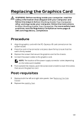
... card with the PCI-Express x16 card connector on the system board.
2 Place the card in the connector and press down firmly. Ensure that the card is firmly seated.
3 Replace the screws that secure the graphics card to the chassis. 4 Connect the power cables to the graphics card.
NOTE: The location of the power supply connector varies depending on the video card installed...
Service Manual - Page 72
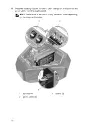
6 Press the releasing clips on the power-cable connectors to disconnect the power cables from the graphics card.
NOTE: The location of the power supply connector varies depending on the video card installed.
1 screw cover 3 power cables (2)
2 screws (2)
72
Service Manual - Page 74
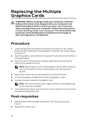
... your computer, follow the instructions in After Working Inside Your Computer. For more safety best practices, see the Regulatory Compliance home page at dell.com/regulatory_compliance.
Procedure
1 Locate the graphics (PCI-Express x16 (SLOT5)) connector on the system board. For more information on the graphics connector, see "System Board Components".
2 Align the graphics card with the PCI-Express...
Service Manual - Page 77

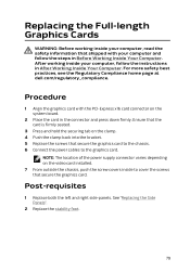
7 Press the releasing clips on the power-cable connectors to disconnect the power cables from the graphics card.
NOTE: The location of the power supply connector varies depending on the video card installed.
1 screw cover 3 power cables (2)
2 screws (2)
77
Service Manual - Page 79
... steps in Before Working Inside Your Computer. After working inside your computer, follow the instructions in After Working Inside Your Computer. For more safety best practices, see the Regulatory Compliance home page at dell.com/regulatory_compliance.
Procedure
1 Align the graphics card with the PCI-Express x16 card connector on the system board.
2 Place the card in the connector and press...
Service Manual - Page 107
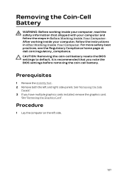
... the BIOS settings to default. It is recommended that you note the BIOS settings before removing the coin-cell battery.
Prerequisites
1 Remove the stability foot. 2 Remove both the left and right side-panels. See "Removing the Side
Panels". 3 If you have multiple graphics cards installed, remove the graphics card.
See "Removing the Graphics Card".
Procedure
1 Lay the computer on...
Service Manual - Page 109
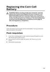
... instructions in After Working Inside Your Computer. For more safety best practices, see the Regulatory Compliance home page at dell.com/regulatory_compliance.
Procedure
Insert the battery into the socket with the side labeled + facing up and press down the battery in the socket.
Post-requisites
1 If you have multiple graphics cards installed, replace the graphics cards...
Service Manual - Page 110
... dell.com/regulatory_compliance.
Prerequisites
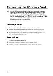
1 Remove the stability foot. See "Removing the Stability Foot". 2 Remove both the left and right side-panels. See "Removing the Side
Panels". 3 If you have multiple graphics cards installed, remove the graphics card.
See "Removing the Graphics Card".
Procedure
1 Lay the computer on the left side. 2 Disconnect the antenna cables from the wireless card...
Service Manual - Page 121
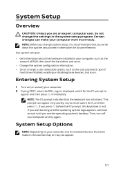
...Set or change a user-selectable option, such as the user password, type of hard drive installed, enabling or disabling base devices, and so on.
Entering System Setup
1 Turn on (or restart) your computer. 2 During POST, when the DELL logo is displayed... system's desktop. Then, turn off your computer and try again.
System Setup Options
NOTE: Depending on your computer and its installed devices, the ...
Service Manual - Page 122
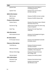
...:ss format.
Displays the BIOS version number. Displays the BIOS release date.
Displays the product name. Default: Alienware Area-51 R2. Allows you to enter the service tag of your computer. Displays the asset tag of your computer.
Displays the Management Engine firmware version.
Displays the Embedded Controller firmware version.
Displays the total computer memory installed. Displays the amount of...
Service Manual - Page 123
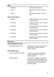
...L3
Device Information SATA Port1 SATA Port2 SATA Port3 SATA Port4 SATA Port5 SATA Port6
Advanced Advanced BIOS Features
OptionRom Display Screen
CPU Configuration Hyper-Threading Technology
XD Bit Capability
Displays the CPU speed. Displays the processor L2 cache size. Displays the processor L3 cache size.
Displays the SATA 1 drive installed in the computer. Displays the SATA 2 drive installed in...
Service Manual - Page 132
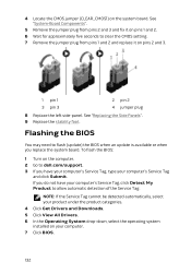
.... See "Replacing the Side Panels". 9 Replace the stability foot.
Flashing the BIOS
You may need to flash (update) the BIOS when an update is available or when you replace the system board. To flash the BIOS:
1 Turn on the computer. 2 Go to dell.com/support. 3 If you have your computer's Service Tag, type your computer's Service Tag
and click Submit. If you do not have your...
Service Manual - Page 133
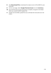
8 Click Download File to download the latest version of the BIOS for your computer.
9 On the next page, select Single-file download and click Continue. 10 Save the file and once the download is complete, navigate to the folder
where you saved the BIOS update file. 11 Double-click the BIOS update file icon and follow the instructions on the
screen.
133